
Peira ST02.45.NS 8 channel electrodes
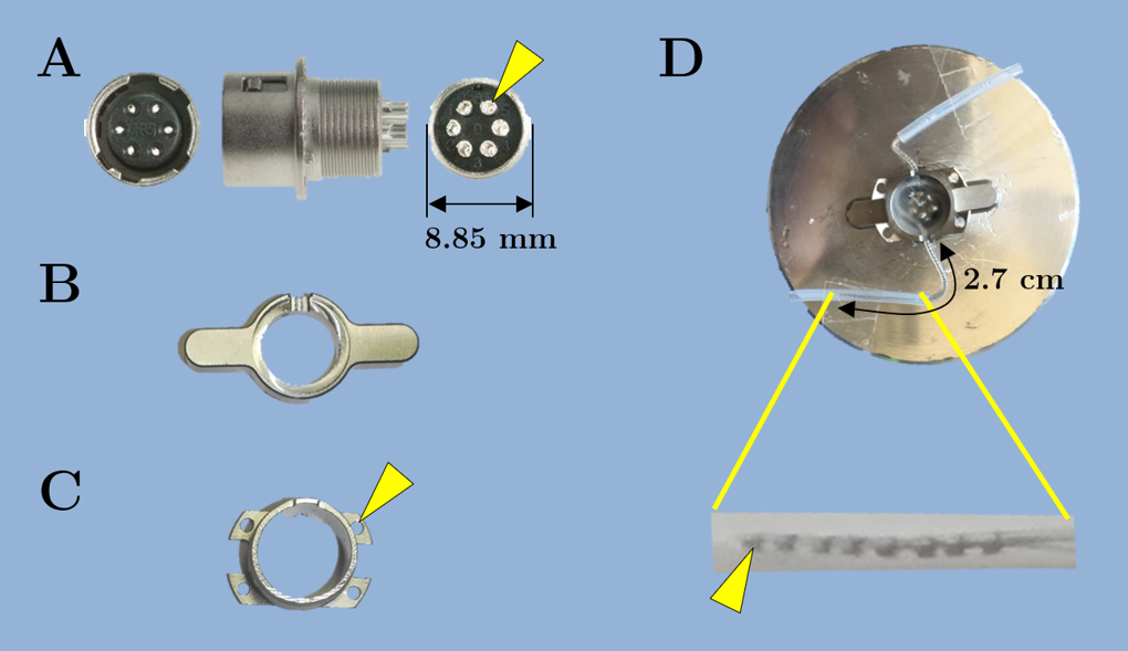
A female six-pole push-pull connector (Figure A) was used for the head connector to connect to the CI arrays. Four pins — two for each side — on the connector were utilized. Pins ‘1’ and ‘2’ were connected to 1st and 2nd rings from the tip of one electrode array, respectively. Similarly, pins ‘3’ and ‘4’ were connected to the two rings of the second array. To assist easy disassembly of the push-pull connector from the stimulator setup, a nut with two flat wings (Figure B) was glued to the connector. This helped in disconnecting the connector by pushing down on the wings and pulling up the male push-pull connector. Finally, a four-hook T-nut (Figure C) was glued. Each hook had a hole that allowed to connect the head connector to the skull using a screw. The hooks were bent slightly to adapt them to the curved shape of the skull. The electrode length kept outside the connector was measured to be 2.7 cm. Rest of the electrode was looped inside the T-nut and secured in place using dental cement. A finished implant should have impedances between 2-3.5kΩ. A finished assembly of a CI head connector is shown in Figure D.