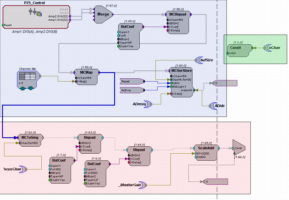
The graphic here shows the RCX circuit MC-fixedInterval-8x8-ViventiECOG_6k used from recording multichannel data from a 64 channel ECoG electrode. For clarity I have highlighted the different parts in different colors.

The blue part records data from the electrode headstage amp (PZ5_Control) into a buffer (MCSerStore). Because we connect two Intan 32 channel preamps to our 64 channel Vivienti electrodes, we have two 32 channel lines come out of the amp and these are merged into a 64 channel signal. That signal is high-passed at 5 Hz. (BufCoef, MCBiquad). If you don't want that much high-passing, adjust this in the circuit you use for your experiment! The MCMap is there for channel remapping, so that the channels are arranged in an order that is anatomically sensible. If the mappings in the associated data table are not appropriate, your topography will be wrong. The bufSize partag allows the Python program to know how big our data buffer is so that it can deal with buffer overruns. (The buffer will automaticall wrap around when it overruns). The ADidx tag allows us to find out how much of the data has been filled, and the ADmsig tag serves to pull the recorded data from the RZ2 circuit to the computer.
The red part is simply for generating audio feedback during the experiment. A single channel is selected and bandpass filtered and scaled for volume (ScaleAdd) before being output to one of the RZ2's analog outputs, which can then be connected to a monitor speaker or headphone. Note that, in the example here, the bandpassing is set for 300 to 3000 Hz, which works well if you want to listen to multiunit has on a microelectrode but may be less useful for an ECoG macorelectrode. May be worth adjusting the values in the BufCoefs. The focusChan and ec_MonitorGain tags are to provide user interfaces for audio monitor channel selection and volume setting.
The green part is simply to allow the program to know how any channels to expect in the multichannel signal. If you adapt this circuit to run with a different type of electrode then it is essential that you change the ConstI value to reflect the number of channels recorded.
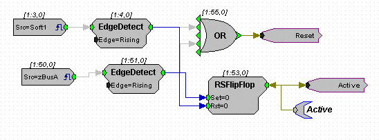
Further down in the circuit there is also the following logic which serves to switch data acquisition on and off by sending a zBUS trigger or a soft trigger 1 respectively:


