Calcium Imaging Set Up
We can briefly summarize the Ca++ set-up in the following components, see Fig1 (Our setup uses hardware from Thorlabs):
- 490 nm Light Source
- A dichroic mirror that reflects light at 45° towards the objective and, consequently, the rat auditory cortex. It also allows the fluorescence pass towards to the camera. (MD499 GFP Dichroic Filter, Refl. Band = 470-490 nm, Trans. Band = 508-675 nm)
- An emission filter to reduce at the minimum the passage of any other light that is not in the designed wavelength range (MF525-39, CWL = 525nm, BW = 39nm)
- The Camera, which will capture and save the images in the computer.
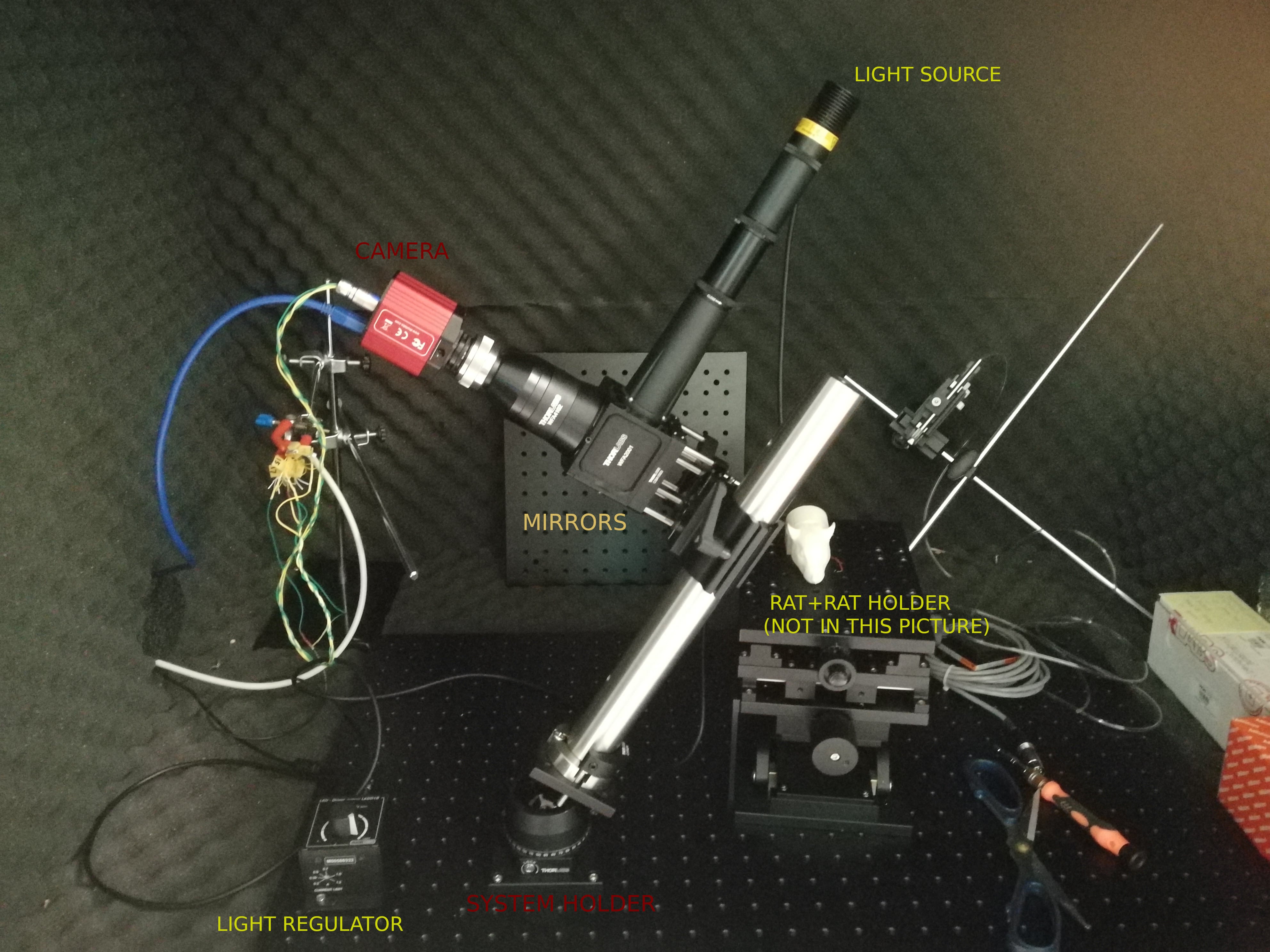
Fig1. Photo of the Ca++ imaging set-up. Please consider that we did not put pictures of "external" set-up such as RZ6 or the computer, which both play a fundamental role for the correct functioning of our set-up.
ZOOM INTO COMPONENTS
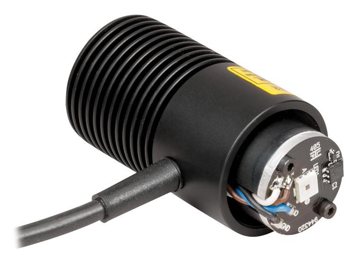
FIG3. M490L4, light source of set up with Wavelength = 490nm
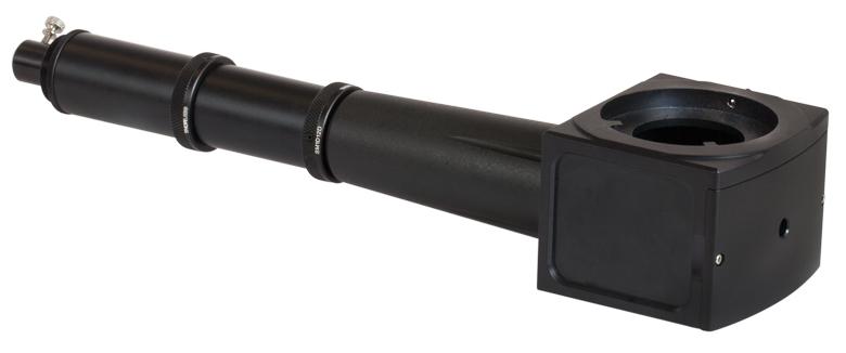
FIG4. WFA2001, Light regulator embedded within the set-up. The left (sth) is controlling the incident light intensity while the right (sth) is controlling the area of spot size.
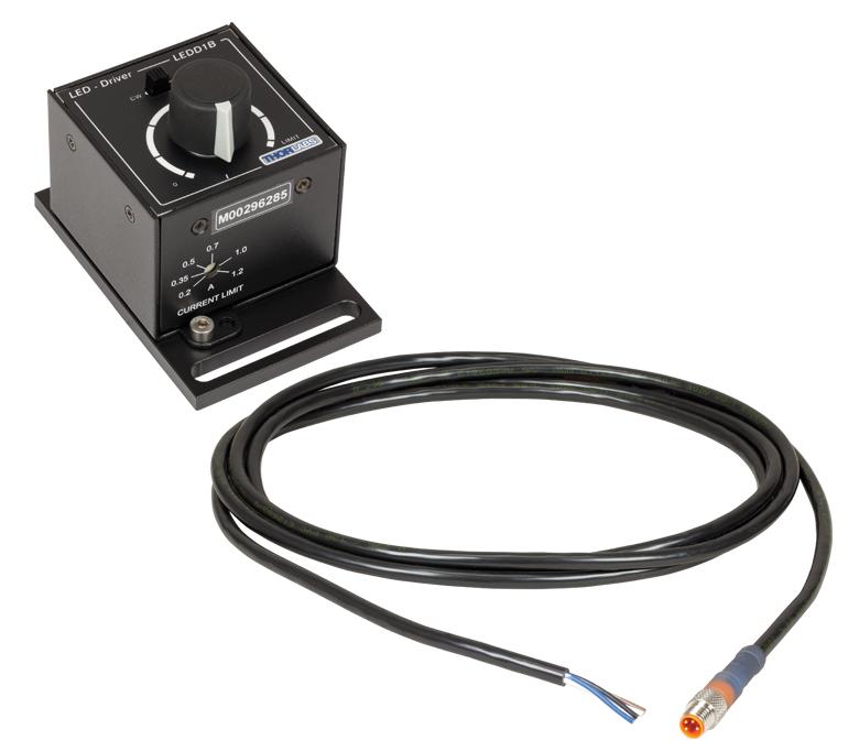
FIG5. LEDD1B Driver is designed to drive high-power LEDs with currents from 200 mA (MILLI AMPERE) to 1200 mA. It features an adjustable LED current limit to protect the connected LED.
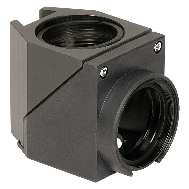
FIG6. MDFM-MF2 system with dichroic mirror and emission filter. Originally, the set-up only included the former. Then, the emission filter was added in order to minimize the risk of cathing other light sources, which can compromise our data collection
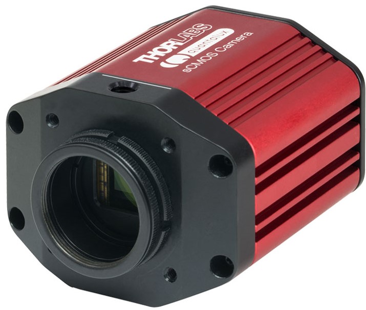
FIG7. CS2100M-USB Camera of our set-up, connected directly with the computer (ADD MORE ABOUT HOW THEY ARE CONNECTED). The pictures will be taken directly by the computer.
Fluorescence Microscope
One of the principles that play an important role in Calcium imaging experiments is the principle of Fluorescence Microscope. Essentially, we want to capture images that are as neat as possible so we need to use a specific wavelength light (green light, 490nm), which origin from a specific light source.
What is the "path" of the light in our set-up (see Fig.2)?
- Light source, which light can be orientated via external commands is shot towards the dichroic mirror.
- Re-directed towards rat's auditory cortex
- The light (that now carries information of neural activity, which in practice means a different wavelength light, see next paragraph ) bounces back towards the objective and the mirrors, but now it can be "dirtied" by other external light sources (gets cleaned by the second mirror in 3 Bis stage)
- The camera takes the picture with (hopefully) clean light, so that we have beautiful and clean images of the Cortex
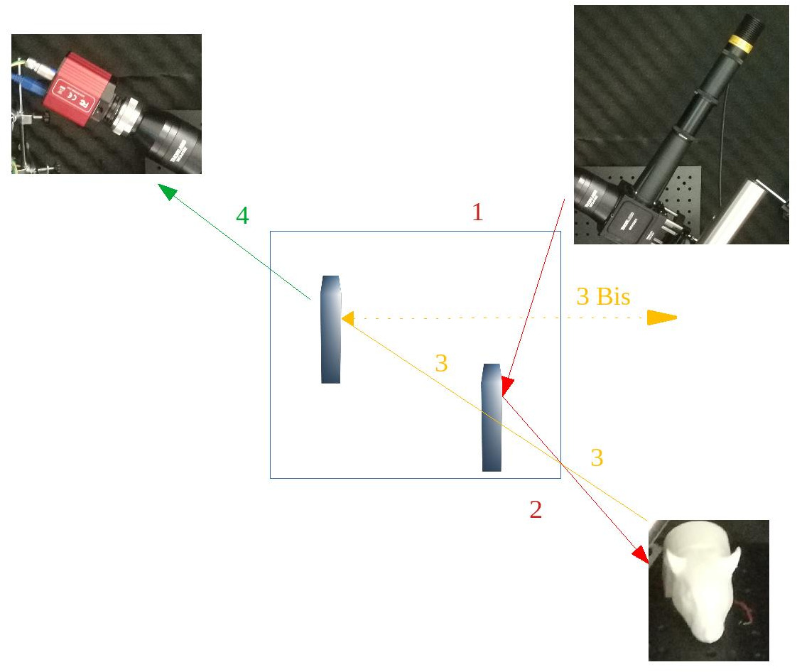
FIG2. Schematic representation of the light "path". The red arrows represent the light from the source to the rat cortex. The yellow ones illustrate the light potentially "dirtied" by other external luminescent sources, cleaned by the second mirror placed in the system (3 Bis). The green arrow represents the light that arrives at the camera, which we want to be as clean as possible because it carries the information from the neural activity in the cortex.
How and why is it so important not to allow all kind of light to reach the camera?
As described previously the set-up counts of 2 mirrors:
- Dichroic mirror, which function is to redirect the light from the Source to the objective and, consequently, towards the exposed rat auditory cortex.
- Emission filter, to reduce at the minimum the passage of any other light that is not in the designed wavelength range (<525nm of wavelength)
The emission filter doesn't allow specific kind of light to reach the camera. This means that data collected will undertake a filter process to exclude all the light that is not useful for our data analysis. Overall, we don't want to allow all kind of light to reach the camera to prevent the collection of data unusable for our purposes.
Magnification: what is it and why is it important for us?
In simple words, magnification is how zoomed/enlarged you want your pictures to be.
Physically speaking, it is defined as the ratio between Image size and Objective size, resulting in a pure number.
----> Magnification = Image size (mm)/Objective size (mm)
The reason that makes magnification important for us is that it plays a fundamental role to calculate the Imaging area.
Imaging Area
The imaging area is the dimension of area taken as picture by our camera. To do so, there are parameters that have to be considered for proper calculation of imaging area, which included the previously mentioned magnification.
Imaging area = CMOS size/(Camera tube magnification x Objective magnification)
- CMOS size represents the sensor size of the camera (complete product details/specs/imaging area), which in our case is (9.6768 x 5.4432)mm
- Camera tube magnification and objective magnification depend on what kind of tube and objective we plan to use. Right now we have 2 per kind, but we are only using in our set-up WFA4102 (scroll until "camera tubes" section in the Overview for technical details) as tube and TL2X-SAP as objective. The respective Magnification values are 0.5 and 2.
So, right now, if we put numbers instead of names, our Imaging area will be:
Imaging area = [9.6768/(0.5/2)] x [5.4432/(0.5/2)] = 9.6768 x 5.4432

