

A. Introduction to RZ6 Multi-I/O Processor
- RZ6 Multi-I/O Processor (RZ6) is a high-frequency auditory signal processor that handles real-time signal generation, acquisition, filtering, and analysis.
- In the Calcium Imaging setup, RZ6 would act as the intermediate bridge between each component or device in the Calcium imaging experiment and the central computer. It controls and receives the hardware status and has been controlled by the main Python program.
- The RZ6 would simultaneously control the exposure part of the camera, the LED light source in the fluorescence microscope, and the auditory signal for the headphones. It also receives the real-time response of the status of these components and returns the responses back to the computer.
- Both the camera and the LED controller in the microscope would be connected to the Digital I/O port at the RZ6 front panel. In addition, optical fiber would also be used to connect the main computer and the back panel of RZ6. Detailed explanation of the pin arrangement of the Digital I/O port and connection would be discussed in the next part.
- (Reserved for introducing the sound generation for the experiment)
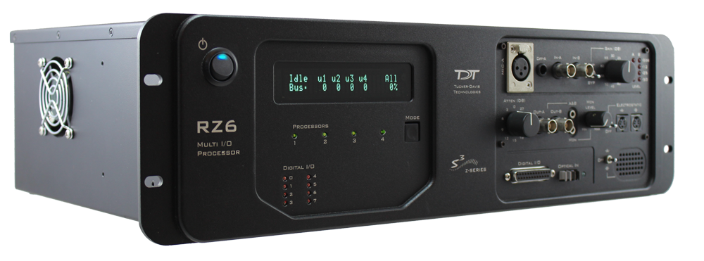
FIG. 1. The front-left view of the RZ6 Multi-I/O Processor (RZ6).
B. Pin Diagram and Connection in RZ6 Multi-I/O Processor
- Since Digital I/O port would be used to connect those components with the RZ6 itself, it is important to know the pin diagrams of the Digital I/O port in RZ6, Auxiliary I/O port in the camera, and the LED controller.
- The following figures show the front view of the Digital I/O port in RZ6 and the pinout diagram respectively:
 |
 |
|
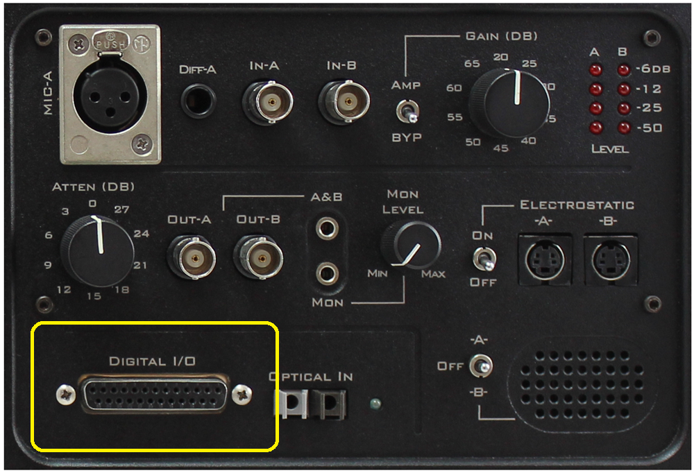
FIG. 2. The front view of the RZ6 panel. The Digital I/O port, which is adapting a 25 pin D-Sub connector or printer port (parallel port) *, is highlighted and located at the bottom-left part. |
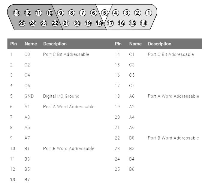
FIG. 3. The DB25 Digital I/O Pinout diagram. There are three sets of addressable, including Port A and B for word addressable, and Port C for bit addressable **. Pin 5 is for digital I/O ground. |
- In the Calcium imaging setup, only the bit addressable (Port C) would be used to communicate with other devices. Thus, it is not necessary to use the word addressable in Port A and B.
- The details of the connection and function of these port C pins is showed in the table below:
| RZ6 Pin | Name | Function | IN / OUT | Connected Components |
| 5 | GND | The ground of the circuit and signals | GND | Other GND cables |
| 14 | C1 | Trigger the exposures of the camera to start the recordings. | Input | Pin 5 in Camera Auxi. I/O |
| 15 | C3 | Trigger the LED controller together with 490nm LED. | Input | |
| 16 | C5 | Strobe OUT signal to determine continuous actual sensor exposure. | Output | Pin 4 in Camera Auxi. I/O |
| 17 | C7 | Frame Valid signal to determine the recorded frames. | OUtput | Pin 12 in Camera Auxi. I/O |
- With the “Adjust Properties for RZ6 Control” in the RPvdsEx program, the data direction could be assigned so that the data direction in Digital I/O would match the above setup. Further information would be provided in the Software chapter.
- If the system is well-set, the digital I/O LED indicator would show the correct sequence as below figure. The green lights are representing Input signal ports while the red lights are indicating Output signal ports.
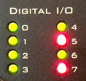
FIG. 4. Correct sequence of LED in the front panel of RZ6 for Calcium Imaging experiment. The green LED lights in C0, C1, C2, C3, C4, and C6 are representing the data direction of these pins is INPUT. The red LED lights in C5 and C7 indicated that the data direction of these pins is OUTPUT.
C. Pin Diagram and Connection in the Camera and LED controller
- The auxiliary connector on the camera allows the user to access optional camera control and internal status signals. The Pin diagram and descriptions are shown below (only pin and signal using in the Calcium imaging experiment would be described):
 |
 |
|
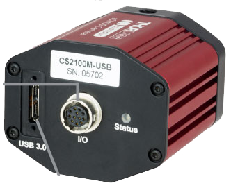
FIG. 5. Back panel connections for the CS2100M-USB Compact Quantalux Camera. (From left to right) USB 3.0 Micro B Port connected with the computer, 12-Pin Hirose Female Connector connected with the RZ6 Multi-I/O Processor, LED status light. |
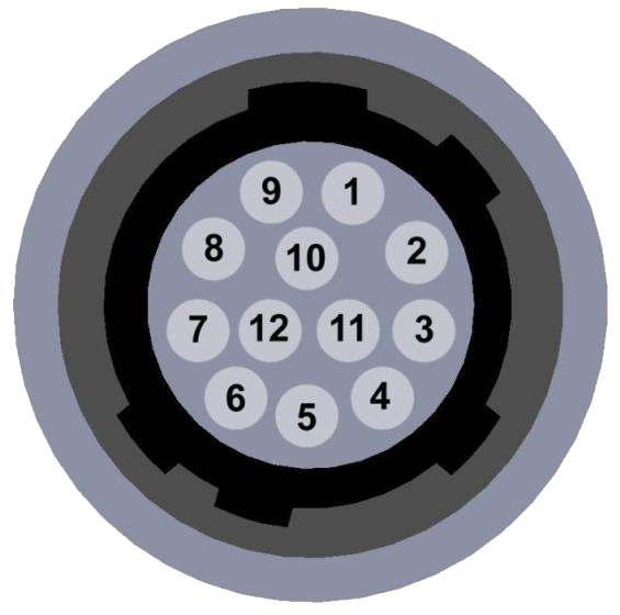
FIG. 6. Illustration of the Auxiliary Connector (Female 12-Pin Hirose Connector) on the rear of the camera. The mating connector for the rear panel connector is HIROSE HR10-10P-12P (73). |
| Pin no. | Name | Function | Connected Components |
| 1 | GND | The ground of the circuit and signals | Other GND cables |
| 2 | GND | The ground of the circuit and signals | Other GND cables |
| 3 | GND | The ground of the circuit and signals | Other GND cables |
| 4 | LVTTL STROBE_OUT | Strobe OUT signal to determine continuous actual sensor exposure. | C5 in RZ6 Digital I/O Port |
| 5 | LVTTL TRIGGER_IN | Trigger the exposures of the camera to start the recordings. | C1 in RZ6 Digital I/O Port |
| 12 | LVTTL FLAL_OUT | Frame Valid Output signal to determine the recorded frames. | C7 in PZ6 Digital I/O Port |
- The connection of LEDD1B LED Driver is much simpler than the above devices.
- Soldering Pin 5 of Digital I/O Port in RZ6 and Modulation-IN Port in LED Driver, the RZ6 could fully take the controls of the LED light and work simultaneously with the camera during recording.
- The following figures show the back view of the LEDD1B LED Driver and the pinout diagram of the Modulation-IN port respectively:
 |
 |
|
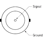
FIG. 6. Back panel connections for the LEDD1B LED Driver. (From left to right) DC 15V 1A power supply, MOD IN port for triggering, LED connector. |
FIG. 7. BNC Female port for Modulation-IN signal. Although it supported 0 to 5 V external LED control, it would be used for the digital triggering signals only. |